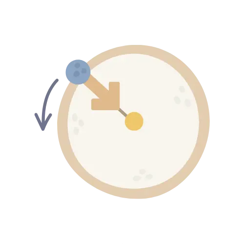

Compute angular displacement from initial and final position, from angular velocity and time, or from arc length and radius, with results in radians, degrees, revolutions and gradians.
Δθ = θ − θ₀, where θ₀ is the initial angular position and θ is the final angular position. This is the direct definition of angular displacement.Δθ = θ − θ₀. The sign tells you direction: positive is counter-clockwise, negative is clockwise (following the standard convention). Units are converted to radians internally.Δθ = ω × t for constant angular velocity. If you supply an initial position θ₀, the calculator also reports final position θ = θ₀ + Δθ.Δθ = s / r, where s is arc length and r is radius. The result is automatically in radians because the arc-length relationship is defined that way. This is the geometric definition of angular displacement.| Unit | Symbol | Value |
|---|
| Property | Value |
|---|
| Quantity | Value |
|---|
| # | Δθ (rad) | Input | Time |
|---|
-
Select a citation style above. Click the citation text to select it all, then copy.
ADVERTISEMENT










Founder & CEO, Toolraxy
Faiq Ur Rahman is a web designer, digital product developer, and founder of Toolraxy, a growing platform of web-based calculators and utility tools. He specializes in building structured, user-friendly tools focused on health, finance, productivity, and everyday problem-solving.
User Ratings:
ADVERTISEMENT
ADVERTISEMENT
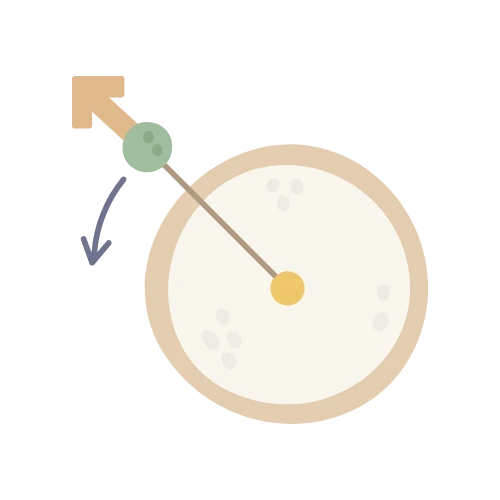
Angular displacement (Δθ) is the change in an object’s angular position over a rotation. It’s measured in radians in SI, though degrees, revolutions, and gradians are common in practice. The sign carries direction: positive for counter-clockwise, negative for clockwise, following the standard convention . Unlike angular distance, which accumulates regardless of direction, displacement is a vector-like quantity returning to the starting orientation gives zero displacement even if the object spun several times.
The concept sits at the foundation of rotational kinematics. Every problem that involves a spinning object, a wheel rolling, a robot arm swinging, a shaft indexing to a new position starts with angular displacement. The three calculation routes the tool offers correspond to the three ways Δθ shows up in practice: you measure two positions directly, you integrate a known angular velocity over time, or you work backward from a measured arc length on a known radius.
Pick the mode that matches what you know, enter the values, and the result populates as you type. Here’s the sequence for each path:
Choose Position change if you have two measured angles. Enter θ₀ and θ, select the unit for each (they can differ), and read Δθ.
Choose Angular velocity if you know the spin rate and how long it acted. Enter ω, pick its unit, enter the time in seconds, and optionally add an initial position to get the final angle.
Choose Arc length & radius if you can measure a distance along the rim and the radius. Enter both in compatible length units—or different ones, the tool converts.
Check the hero output: Δθ in radians is the primary result, with the verdict banner explaining whether it’s a small adjustment, a partial turn, or multiple revolutions.
Scan the unit table for the same angle in degrees, revolutions, gradians, arcminutes, and arcseconds.
Use the derived quantities block for direction, turns completed, or final position depending on the mode.
Each mode has its own one-line relationship. Position change: Δθ = θ − θ₀, where θ and θ₀ are final and initial angular positions in radians. Constant angular velocity: Δθ = ω × t, where ω is in rad/s and t is in seconds. Arc geometry: Δθ = s / r, where s is arc length and r is radius, both in the same length unit .
The tool’s conversion layer handles mixed units before any arithmetic. Degrees multiply by π/180 to reach radians. Revolutions multiply by 2π. Gradians multiply by π/200. Angular velocity in RPM multiplies by 2π/60. Lengths convert through a meter-based table: inches multiply by 0.0254, feet by 0.3048, miles by 1609.344. No rounding happens until the display stage, so the radian value that feeds the unit table is computed at full double precision. The tool does not model variable angular velocity, acceleration, or non-circular paths. The velocity mode assumes constant ω over the interval. If your rotation accelerates, the average ω you enter will give average displacement, not the instantaneous value at either endpoint.
A machinist needs to rotate a workpiece from 30° to 215° on a rotary table. In position-change mode, enter θ₀ = 30° and θ = 215°. The tool converts both to radians (0.5236 and 3.7525), subtracts, and returns Δθ = 3.2289 rad. The unit table shows 185° (the same as the direct subtraction, which is a useful sanity check), 0.5139 rev, and 205.56 grad. The verdict banner reads “more than a half turn but less than a full revolution” accurate, since 185° sits between 180° and 360°.
Now switch to velocity mode. A motor spins a shaft at 12 rev/s for 3.5 seconds. Enter ω = 12 and select rev/s, t = 3.5. The tool converts 12 rev/s to 75.40 rad/s, multiplies by 3.5, and returns Δθ = 263.89 rad. The derived block reports 42 full turns plus a remainder, or 42.0 rev as a decimal. If you add an initial position of 0 rad, the final position shows 263.89 rad, which wraps to 263.89 − 42×2π = 0.00 rad, the shaft happens to land back near its starting angle after exactly 42 revolutions, which is a coincidence of the numbers but a useful illustration of how displacement accumulates beyond 2π.
The table below gives order-of-magnitude displacement values for rotations you might encounter. These are reference ranges from published device specifications and standards, not tool outputs. They’re useful when you need a starting point for an expected Δθ before you have measured values.
| Context | Typical angular displacement range |
|---|---|
| Standard hobby servo (RC) | 180° total, or ±90° from center |
| Industrial robot joint (typical axis) | 220°–330° per joint, varies by axis and manufacturer |
| Multi-turn precision potentiometer (10-turn) | 3,600° (10 full revolutions) |
| Single-turn potentiometer (standard) | 270°–300° typical mechanical range |
| Stepper motor full step (1.8° motor) | 1.8° per step, 200 steps per revolution |
| Rotary variable differential transformer (RVDT) | ±30°–70° linear range, full 360° rotation possib |
Δθ = θ − θ₀ when you know start and end angles, Δθ = ω × t for constant angular velocity over time t, or Δθ = s / r when you know arc length and radius. The three are equivalent ways of describing the same rotation.
Multiply angular velocity by the time interval: Δθ = ω × t. If ω is in rad/s and t is in seconds, the result is in radians. The calculator converts ω from deg/s, rev/s, or RPM to rad/s before multiplying, so you can enter the units you have.
The SI unit is radians (rad). Degrees, revolutions, and gradians are common in engineering and everyday use. The calculator reports all six units radians, degrees, revolutions, gradians, arcminutes, and arcseconds from a single input.
Yes. A negative Δθ means the final angular position is clockwise from the initial position under the standard convention. It does not mean the rotation was “wrong” it means the direction is opposite to the positive convention .
Angular velocity (ω) is the rate of change of angular position, measured in rad/s. Angular displacement (Δθ) is the accumulated change over an interval, measured in rad. Velocity tells you how fast the angle is changing; displacement tells you how much it changed.
Divide the arc length by the radius: Δθ = s / r. If the arc is 0.5 m and the radius is 2 m, Δθ = 0.25 rad. The result is automatically in radians because the arc-length relationship defines the radian that way.
A full circle is 2π radians, or 360°, or 1 revolution, or 400 gradians. The calculator will report whichever unit you select, and the unit table shows all of them at once.
Yes. In two-dimensional problems, the sign encodes direction: positive for counter-clockwise and negative for clockwise. In three dimensions, angular displacement is better described as a pseudovector along the axis of rotation, but the calculator works in the scalar two-dimensional convention.
The tool does not wrap Δθ to a single turn. If a shaft spins 5 times, Δθ is 10π rad (about 31.4 rad), not a value between 0 and 2π. This matches the physical accumulation of rotation and is useful for counting turns, but you’ll need to apply modulo if you want a dial position.
Yes, for the displacement calculation itself. Enter the joint’s start and end angles in position-change mode. The tool’s output is the net angular displacement. It does not account for joint limits, backlash, or control system behavior—those are separate engineering considerations.
The National Institute of Standards and Technology‘s NIST Guide to the SI provides the framework for the radian and degree conversions used throughout the calculator, though the specific factors follow the standard definitions of π and the gradian.
OpenStax College Physics defines angular displacement as the change in angular position and derives the relationship Δθ = s/r for circular motion, the basis of the arc mode.
ADVERTISEMENT
ADVERTISEMENT